Step 3/4. Step 3: Substituting the value of I1 I 1 into equation (1), we get: 1.0 +I2 = 3.0 1.0 + I 2 = 3.0. Solving this equation gives us I2 = 2.0 I 2 = 2.0 A. Answer. Step 4: Finally, we apply Kirchhoff’s Voltage Law in the second loop to find the unknown EMF.
Solved The ammeter in (Figure 1) reads 5.0 A. -Find I1, I2, | Chegg.com
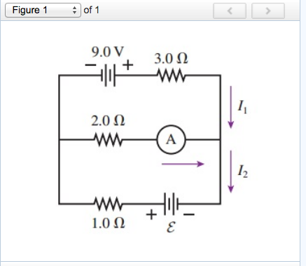
ISBN: 9781305116399 Author: Raymond A. Serway, John W. Jewett Publisher: Raymond A. Serway, John W. Jewett Chapter12: Static Equilibrium And Elasticity Section: Chapter Questions Problem 12.10P See similar textbooks Related questions Question The ammeter in the figure reads 3.0 A. Find I1, I2, and Ɛ.

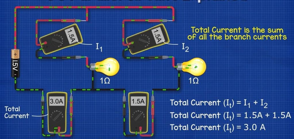
Source Image: theengineeringmindset.com
Download Image
The ammeter reads 5.0A. Find I 1, I 2, and ε Homework Equations ΔV=IR The Attempt at a Solution I’ve never dealt with ammeters before so I’m very confused. To start, I tried breaking this into loops, and then used Kirchhoff’s Law. I started with the left side, since I have the value of the battery. I know that ΣΔV = 0 in this loop.

Source Image: toppr.com
Download Image
The reading of ammeter shown in figure is? 2.Calculate the current through the ammeter. Step 3/6 3.Subtract the current from the ammeter’s reading to get the voltage drop. Step 4/6 4.Find the resistance between points I1 and I2. Step 5/6 5.Multiply the voltage drop by the resistance to get the power loss (in watts). Step 6/6 6.Add the power loss to the ammeter’s reading to get the total

Source Image: youtube.com
Download Image
The Ammeter In The Figure Reads 3.0 A.
2.Calculate the current through the ammeter. Step 3/6 3.Subtract the current from the ammeter’s reading to get the voltage drop. Step 4/6 4.Find the resistance between points I1 and I2. Step 5/6 5.Multiply the voltage drop by the resistance to get the power loss (in watts). Step 6/6 6.Add the power loss to the ammeter’s reading to get the total Ammeters are connected in series with whatever device’s current is to be measured. A series connection is used because objects in series have the same current passing through them. (See Figure 21.28, where the ammeter is represented by the symbol A.) Figure 21.27 (a) To measure potential differences in this series circuit, the voltmeter (V
The reading of the ammeter as per figure shown is (a) \( \frac1{8… – YouTube
3,494 solutions Introduction to Quantum Mechanics 3rd Edition • ISBN: 9781107189638 (2 more) Darrell F. Schroeter, David J. Griffiths 485 solutions More related questions physics Consider the circuit shown in Figure . Determine the current through the 10.0 Ohm resistor. engineering In figure, the ammeter (I) reads a current of \( 10 \mathrm~mA \)… – YouTube

Source Image: m.youtube.com
Download Image
The ammeter shown in the figure below reads 2.00 A. Find I1, I2, and ε. – YouTube 3,494 solutions Introduction to Quantum Mechanics 3rd Edition • ISBN: 9781107189638 (2 more) Darrell F. Schroeter, David J. Griffiths 485 solutions More related questions physics Consider the circuit shown in Figure . Determine the current through the 10.0 Ohm resistor. engineering

Source Image: m.youtube.com
Download Image
Solved The ammeter in (Figure 1) reads 5.0 A. -Find I1, I2, | Chegg.com Step 3/4. Step 3: Substituting the value of I1 I 1 into equation (1), we get: 1.0 +I2 = 3.0 1.0 + I 2 = 3.0. Solving this equation gives us I2 = 2.0 I 2 = 2.0 A. Answer. Step 4: Finally, we apply Kirchhoff’s Voltage Law in the second loop to find the unknown EMF.

Source Image: chegg.com
Download Image
The reading of ammeter shown in figure is? The ammeter reads 5.0A. Find I 1, I 2, and ε Homework Equations ΔV=IR The Attempt at a Solution I’ve never dealt with ammeters before so I’m very confused. To start, I tried breaking this into loops, and then used Kirchhoff’s Law. I started with the left side, since I have the value of the battery. I know that ΣΔV = 0 in this loop.
Source Image: toppr.com
Download Image
The ammeter shown in the figure below reads 2.00 A. Find I1, I2, and ε. – YouTube Suppose you want 10 V to produce a full-scale deflection of a voltmeter containing a 25-Ω galvanometer with a 50-μA sensitivity. Then 10 V applied to the meter must produce a current of 50 μA. The total resistance must be: (20.4.1) R t o t = R + r = V I = 10 V 50 μ A = 200 k Ω.

Source Image: m.youtube.com
Download Image
The ammeter shown in Figure reads 2.00 A. Find I1, I 2, and E. – YouTube 2.Calculate the current through the ammeter. Step 3/6 3.Subtract the current from the ammeter’s reading to get the voltage drop. Step 4/6 4.Find the resistance between points I1 and I2. Step 5/6 5.Multiply the voltage drop by the resistance to get the power loss (in watts). Step 6/6 6.Add the power loss to the ammeter’s reading to get the total

Source Image: m.youtube.com
Download Image
If the reading of ammeter `A_(3)` in figure is 0.75 A. Neglecting the resistances – YouTube Ammeters are connected in series with whatever device’s current is to be measured. A series connection is used because objects in series have the same current passing through them. (See Figure 21.28, where the ammeter is represented by the symbol A.) Figure 21.27 (a) To measure potential differences in this series circuit, the voltmeter (V

Source Image: youtube.com
Download Image
The ammeter shown in the figure below reads 2.00 A. Find I1, I2, and ε. – YouTube
If the reading of ammeter `A_(3)` in figure is 0.75 A. Neglecting the resistances – YouTube ISBN: 9781305116399 Author: Raymond A. Serway, John W. Jewett Publisher: Raymond A. Serway, John W. Jewett Chapter12: Static Equilibrium And Elasticity Section: Chapter Questions Problem 12.10P See similar textbooks Related questions Question The ammeter in the figure reads 3.0 A. Find I1, I2, and Ɛ.
The reading of ammeter shown in figure is? The ammeter shown in Figure reads 2.00 A. Find I1, I 2, and E. – YouTube Suppose you want 10 V to produce a full-scale deflection of a voltmeter containing a 25-Ω galvanometer with a 50-μA sensitivity. Then 10 V applied to the meter must produce a current of 50 μA. The total resistance must be: (20.4.1) R t o t = R + r = V I = 10 V 50 μ A = 200 k Ω.